CTSEET is the documentation website for courses offered by Dr. M. E. AlSharidah. It records all course descriptions, learning outcomes, objectives, syllabus, and notes.
CTSEET is the documentation website for courses offered by Dr. M. E. AlSharidah. It records all course descriptions, learning outcomes, objectives, syllabus, and notes.
This course starts with presentation of source conversion. The chapters thereafter focus on the fundamental theorems of DC electrical network such as mesh analysis, nodal analysis, superposition, Thevenin's and Norton's theorems, maximum power transfer and finally Millman's theorem. The same theorems are repeated for AC electrical networks. Finally, methods for analyzing and calculating electrical quantities of balanced three-phase systems will be discussed.
Robert L. Boylestad, "Introductory Circuit Analysis".
| % | Category | Notes |
|---|---|---|
| 10 | Atendance/Activity | 2.5% will be deducted for every 4hr absense |
| 30 | Quizes | Single problem quiz every 2 weeks |
| 30 | Midterm (Paper based) | problem type questions |
| 30 | Final Exam (Paper based) | problem type questions |
| Event | Date |
|---|---|
| Course starts | Sun 2024-09-16 |
| Last day of classes | Thu 2024-12-19 |
| Course ends | Tue 2025-01-09 |
| Assessment | Date | Topic |
|---|---|---|
| Quiz 1 | Wed 2024-10-02 | (DC) Superposition |
| Quiz 2 | Wed 2024-10-09 | (DC) [Thevenin or Norton] |
| Quiz 3 | Wed 2024-10-16 | (DC) [Mesh or Nodal] |
| Midterm Exam 1 | Wed 2024-10-23 | (DC) [Superposition , Thevenin, Norton, Mesh, Nodal] |
| Quiz 4 | Wed 2024-10-30 | (AC) [Superposition or Thevenin or Norton] |
| Quiz 5 | Wed 2024-11-06 | (AC) [Mesh or Nodal] |
| Quiz 6 | Wed 2024-11-13 | (AC) [Polyphase (Delta-Star)] |
| Midterm Exam 2 | Wed 2024-11-20 | (AC) [Superposition, Thevenin, Norton, Mesh, Nodal] |
| Quiz 7 | Wed 2024-11-27 | Bonus/Make-up |
Course presente by Dr. M. E. AlSharidah during spring of 2025 ↩
Analyze DC electric circuits using superposition theorem.
Analyze DC electric circuits using thevenin's theorem.
Analyze DC electric circuits using mesh analysis.
Analyze DC electric circuits using node analysis.
Analyze AC electric circuits using superposition theorem.
Analyze AC electric circuits using Thevenin's theorem.
Analyze AC electric circuits using mesh analysis.
Analyze AC electric circuits using node analysis.
The following selected chapters give in depth explanation on subjects related to the course.
All course lecture and labs recorded meetings and notes
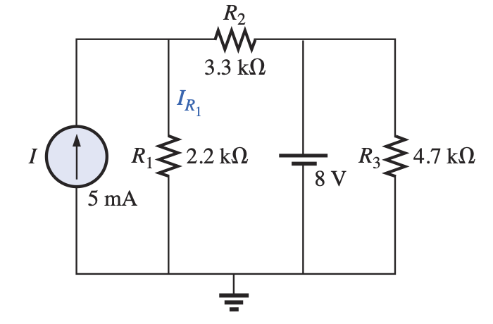
Using simulation as a guide, the circuit parameters will be as in the figue below.
The solution is in two parts. First we turn the battery off and solve for the current in $R_1$. The second part, we turn off the current source and solve for the curent through $R_1$ due to the battery.
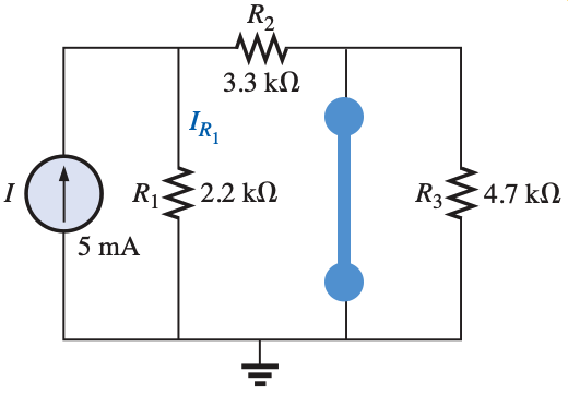
Note that $R_3$ is shorted, and to obtain the current through $R_1$ we will use the current divider rule:
$$\begin{align}\text{Current divider rule: }\rightarrow I'_{R_1} &= \frac{R_2}{(R_1+R_2)}\cdot I \\
&=\frac{3.3 k\Omega}{(2.2 k\Omega + 3.3k\Omega)}\cdot 5mA \\
&=\frac{3.3 k\Omega}{5.5 k\Omega }\cdot 5mA \\
&=0.6\cdot 5mA \\
&=3mA \end{align}$$
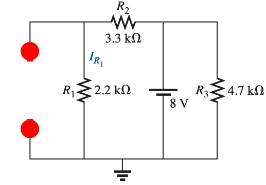
Since $R_3$ is in parallel with the battery, then the voltage across it is the battery voltage and it wont affect the current through $R_1$.
To solver for the current through $R_1$, we will only consider the resistances on the left side of the battery
$$\begin{align}\text{Ohm's Law: }\rightarrow I''_{R_1} &= \frac{E}{(R_1+R_2)}\\
&=\frac{8V}{(2.2 k\Omega + 3.3k\Omega)}\\
&=\frac{8V}{5.5 k\Omega }\\
&=1.455 mA \\
&=1.46 mA \end{align}$$
$$\begin{align*}I_{R_1} &= I'_{R_1} + I''_{R_1} \\
&= 3 mA + 1.46 mA\\
&= 4.46 mA\end{align*}$$
which is the same as
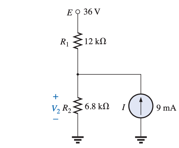
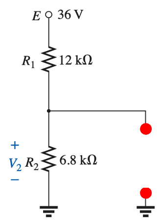
Using simulation as a guide, the circuit parameters will be as in the figue below.
First we turn the battery off and solve for the voltage $V'_2$ across $R_2$. Then we turn off the current source $I$ and solve for the $V''_2$ due to the 36V battery.
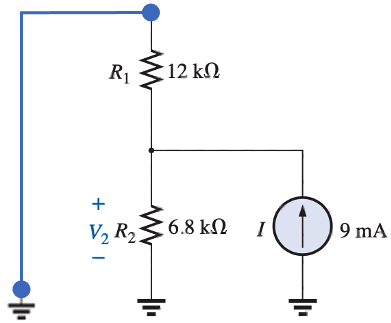
We can use the current divider rule to find the current through $R_2$ then use Ohm's law to find the voltage $V_2$:
$$\begin{align}\text{Current divider rule: }\rightarrow I'_{2} &= \frac{R_1}{(R_1+R_2)}\cdot I \\
&=\frac{12 k\Omega}{(12 k\Omega + 6.8k\Omega)}\cdot 9mA \\
&=\frac{12 k\Omega}{18.8 k\Omega }\cdot 9mA \\
&=0.638\cdot 9mA \\
&=5.745mA\\
\text{Ohm's law: }\rightarrow V'_2 &= R_2 \cdot I'_{2}\\
&=6.8k\Omega \cdot 5.75mA\\
&=(6.8\times 10^3) \cdot (5.75\times 10^{-3})\\
&= 39.06 V\end{align}$$
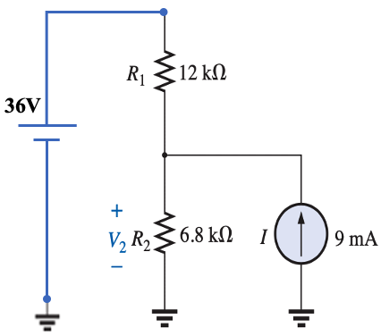
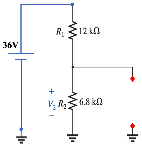
which is equivalent to
Since $R_3$ is in parallel with the battery, then the voltage across it is the battery voltage and it wont affect the current through $R_1$.
To solver for the current through $R_1$, we will only consider the resistances on the left side of the battery
$$\begin{align}\text{Voltage divider rule: }\rightarrow V''_{2} &= \frac{R_2}{(R_1+R_2)}\cdot E\\
&=\frac{6.8 k\Omega}{(12 k\Omega + 6.8 k\Omega)} \cdot 36 V\\
&=\frac{6.8 k\Omega}{18.8 k\Omega } \cdot 36 V\\
&= 13.02 V \end{align}$$
$$\begin{align*} V_2 &= V'_2 + V''_2 \\
&= 39.06 V + 13.02 V\\
&= 52.08 V \end{align*}$$
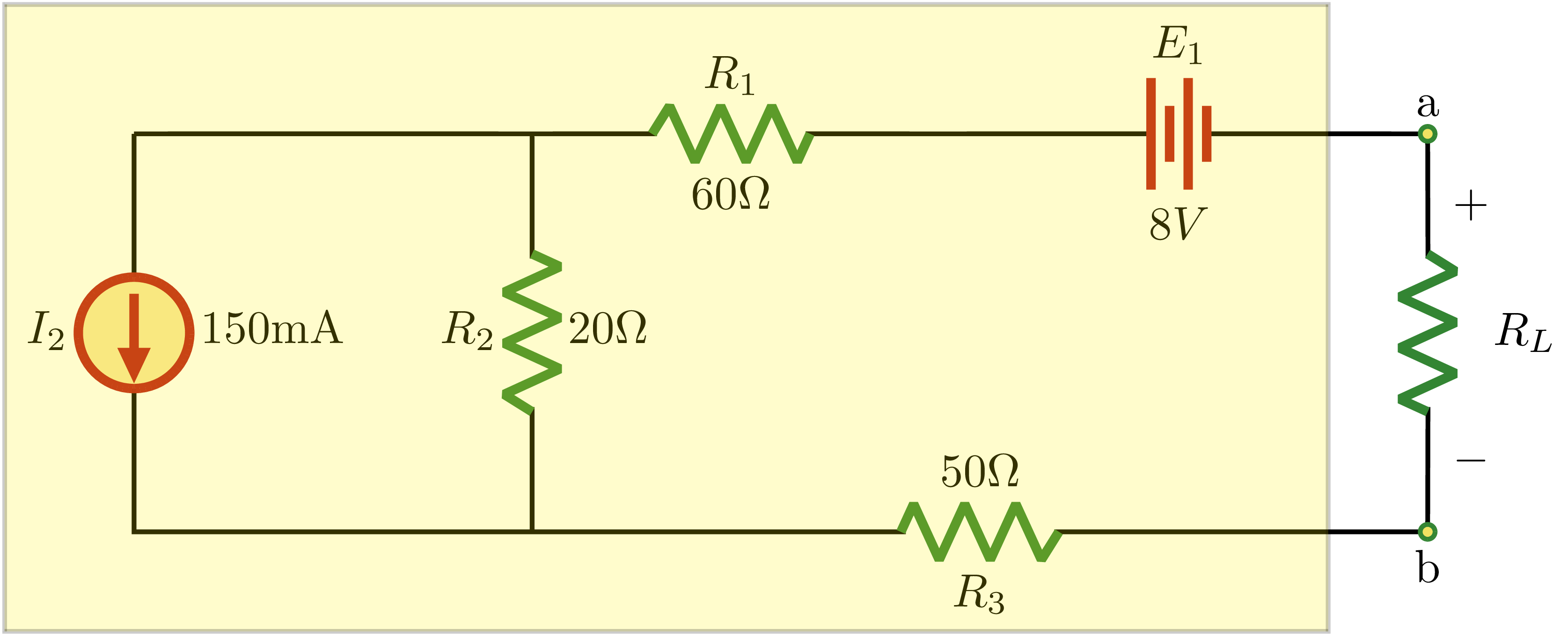
$$\begin{align}
R_{TH} &= R_1 + R_2 + R_3\\
&= 60\Omega + 20\Omega + 50\Omega \\
&= 130\Omega
\end{align}
$$
$$\begin{align}
E_{TH} &= -E_1 -R_2\cdot I_2\\
&= -8V - (20\Omega) \cdot (150 mA)\\
&= -8V - 3V\\
&= -11V
\end{align}
$$
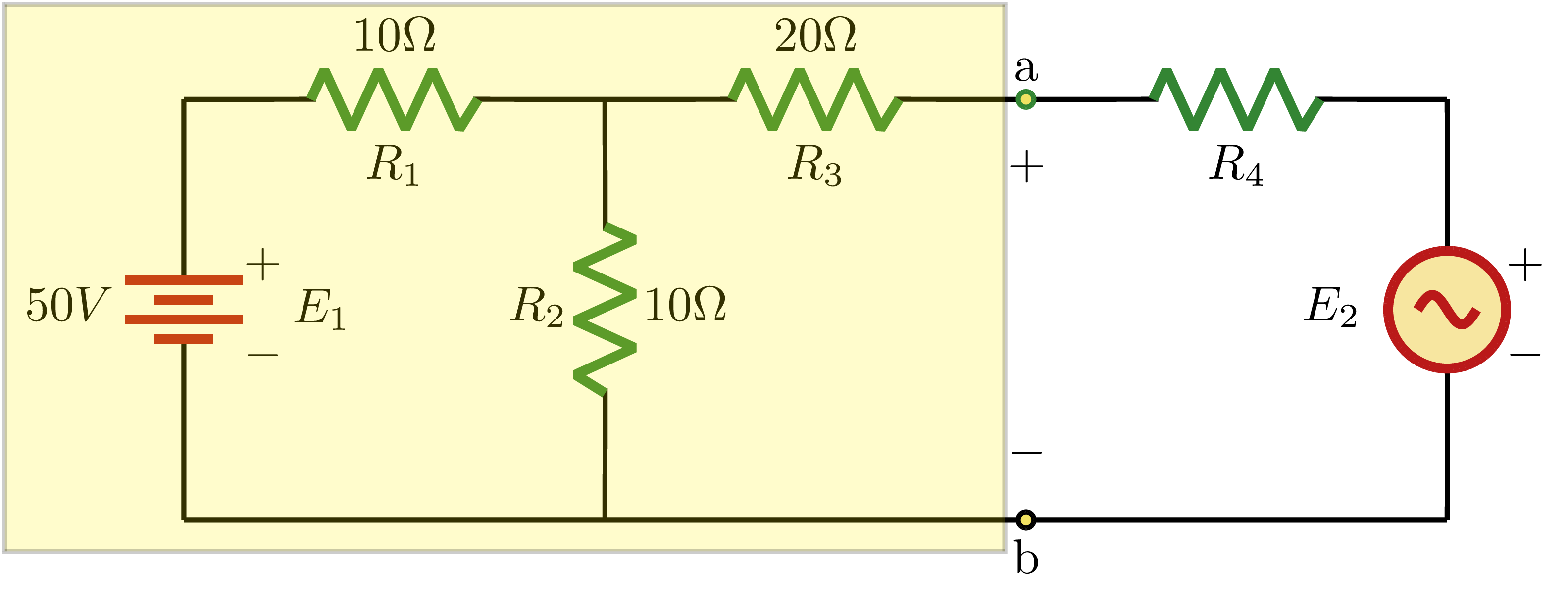
$$\begin{align}
R_{TH} &= (R_1 //R_2) + R_3\\
&= \frac{10\Omega}{2} + 20\Omega \\
&= 25\Omega
\end{align}
$$
$$\begin{align}
\text{Voltage divider rule:} \rightarrow E_{TH} &= \frac{R_2}{R_1+R_2} \cdot E_1\\
&= \frac{10\Omega}{(10+10)\Omega}\cdot 50V\\
&= \frac{10\Omega}{20\Omega}\cdot 50V\\
&= 25V
\end{align}
$$
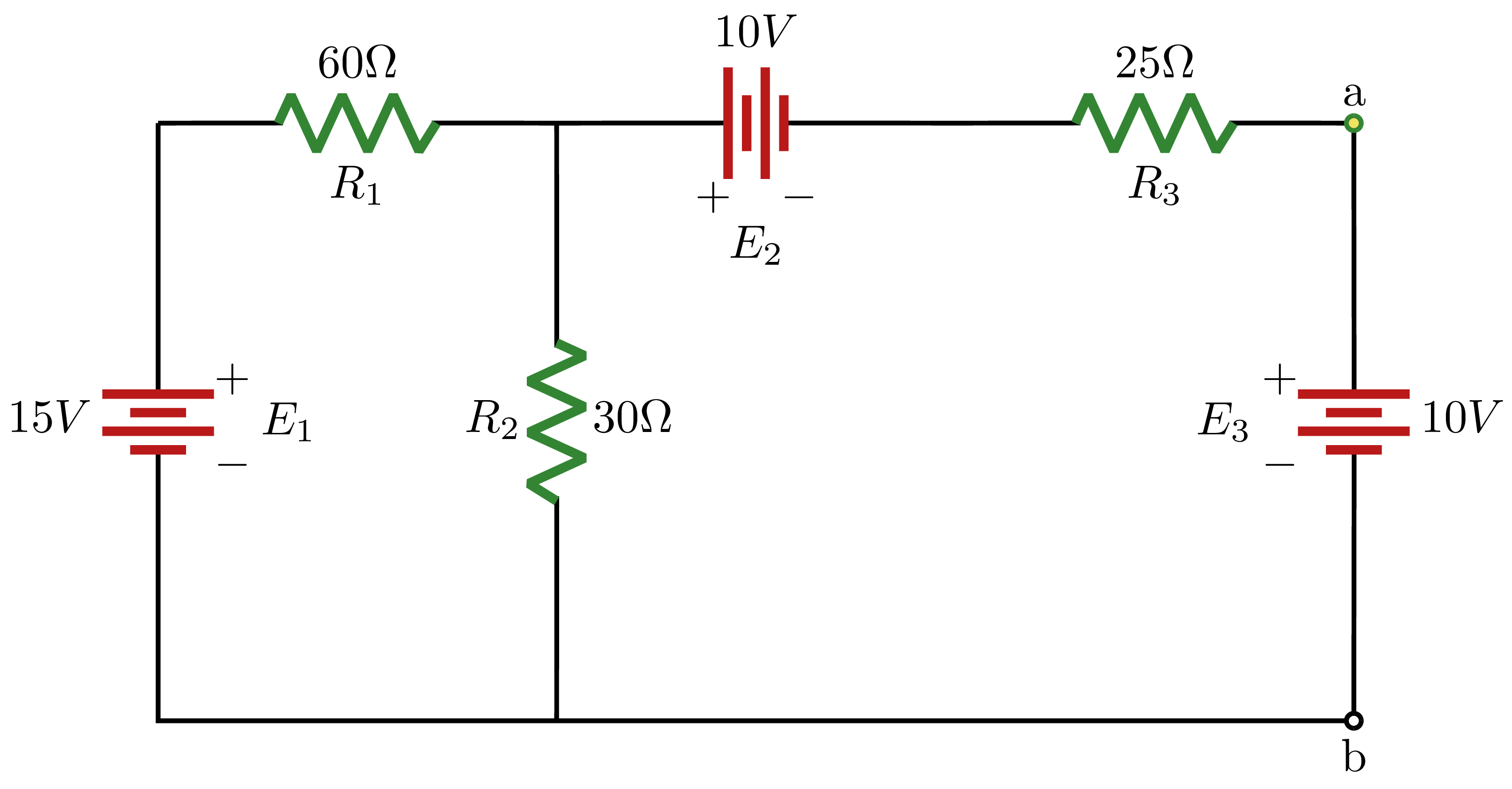
$$\begin{align}
R_{N} &= (R_1 //R_2) + R_3\\
&= \frac{(60\Omega) \cdot (30 \Omega)}{(60\Omega) + (30 \Omega)} + 25\Omega \\
&= 20\Omega + 25\Omega \\
&=45\Omega
\end{align}
$$
$$\begin{align}
\text{Solve for the voltage across $R_2$//$R_3$:} \rightarrow R_{23} &= \frac{R_2 \cdot R_3}{R_2 + R_3}\\
&= \frac{(30\Omega) \cdot (25\Omega)}{30\Omega + 25\Omega}\\
&= 13.64\Omega\\
\rightarrow V_{23} &= \frac{R_{23}}{R_1+R_{23}}\cdot E_1\\
&=\frac{13.64\Omega}{(60+13.64)\Omega}\cdot 15V\\
&=\frac{13.64}{73.64}\Omega\cdot 15V\\
&=2.778V\\
\therefore I'_N &= \frac{V_{23}}{R_3}\\
&=\frac{2.778V}{25\Omega}\\
&=111.1 mA
\end{align}
$$
$$\begin{align}
\text{Solve for the total resistance:} \rightarrow R_{T} &= R_1 // R_2 + R_3\\
&=\frac{R_1 \cdot R_2}{R_1 + R_2}+R_3\\
&= \frac{(60\Omega) \cdot (30\Omega)}{60\Omega + 30\Omega}+25\Omega\\
&= 20\Omega+ 25\Omega\\
&=45\Omega\\
\therefore I''_N &= \frac{-E_{2}}{R_T}\\
&=\frac{-10V}{45\Omega}\\
&=-222.2 mA
\end{align}
$$
$$\begin{align}
I_N &= I'_N - I''_N\\
&=111.1mA - 222.2mA\\
&=-111.1 mA
\end{align}
$$
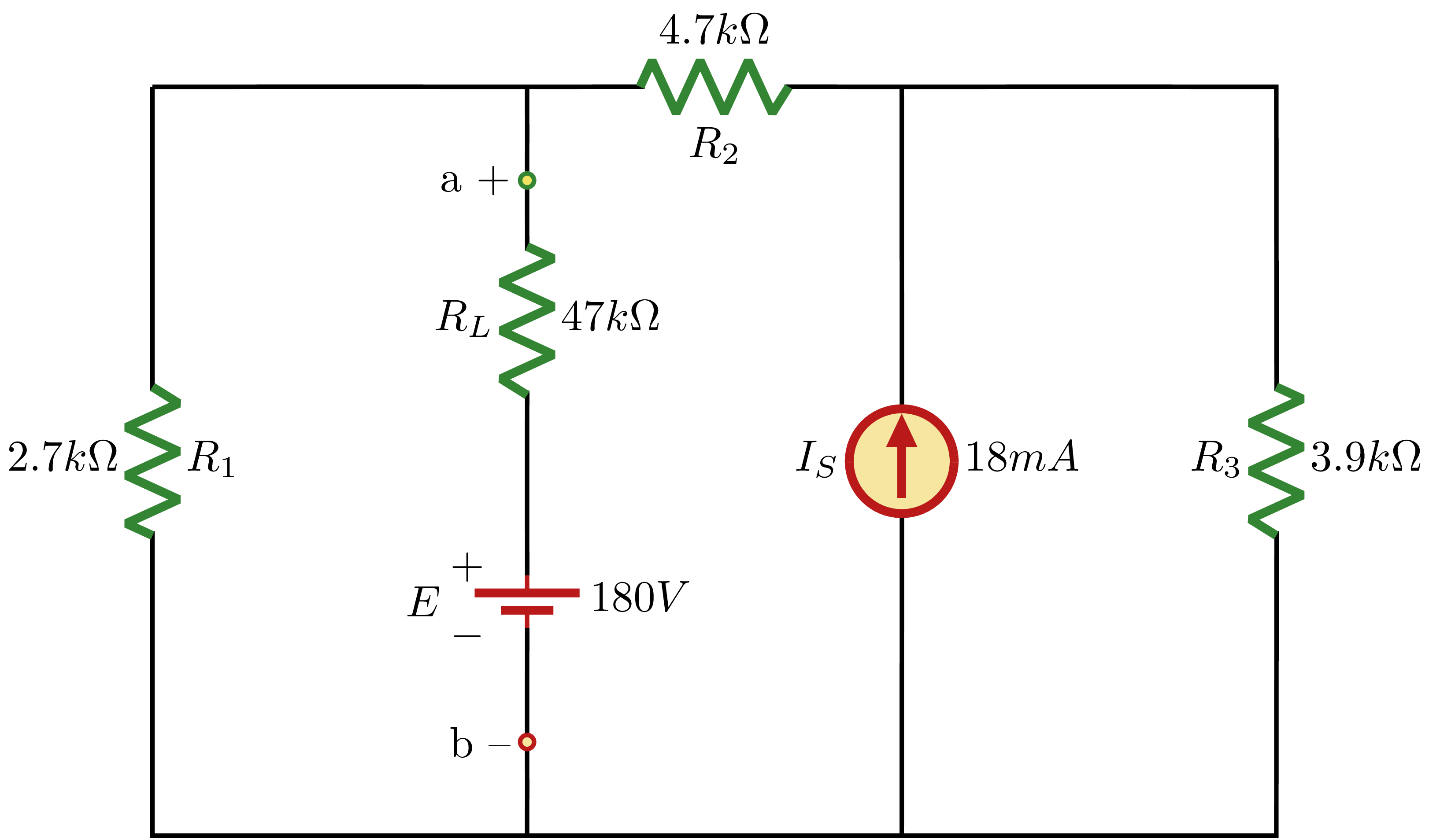
$$\begin{align}
R_{N} &= R_1 //(R_2 + R_3)\\
&= \frac{(2.7k\Omega) \cdot (4.7k\Omega+3.9k\Omega)}{(2.7k\Omega) + (4.7k\Omega + 3.9k\Omega)} \\
&= \frac{(2.7) \cdot (8.6)}{11.3}k\Omega \\
&=2.055k\Omega
\end{align}
$$
$$\begin{align}
\text{Using current divider rule:} \rightarrow I_{N} &= \frac{R_3}{R_2 + R_3}\cdot I_s\\
&= \frac{3.9k\Omega}{4.7k\Omega + 3.9k\Omega}\cdot 18mA\\
&= 0.4535\cdot 18mA\\
&=8.163mA
\end{align}
$$